- Overview
Handheld anti-reconnaissance system is mainly used to search and detect optical observation and targeting devices, such as white/low light sights, telescopes and laser rangefinders within the target area, to determine their direction and distance, and to conduct laser suppression on them. The equipment can be used stand alone, either handheld or mounted, or combined with a handheld display and control terminal for remote operation. Alternatively, it can be mounted on a turntable to enhance the safety and concealment of the user.
- Product Structure
Handheld anti-reconnaissance equipment includes many functional modules, such as laser detection, laser suppression, High-definition observation camera, laser suppression, laser rangefinders, laser alarm, speech recognition, satellite positioning and electronic compass. Accessories include handheld display and control terminals, batteries, chargers, storage and transportation boxes, carrying bags, tripods, etc.
The main components of the system are shown in Table 1
Table 1 Composition of FinderPro-P Handheld Anti-Reconnaissance System
|
S. No.
|
Product name
|
Model
|
Quantity
|
Unit
|
Remarks
|
|
1
|
Handheld anti-reconnaissance equipment
|
FinderPro-P1A
|
1
|
PC
|
|
|
2
|
handheld display and control terminal
|
FinderPro-P2A
|
1
|
PC
|
Optional
|
|
3
|
Distribution box
|
FinderPro-P3A
|
1
|
PC
|
Optional
|
|
4
|
Turntable
|
FinderPro-P4A
|
1
|
PC
|
Optional
|
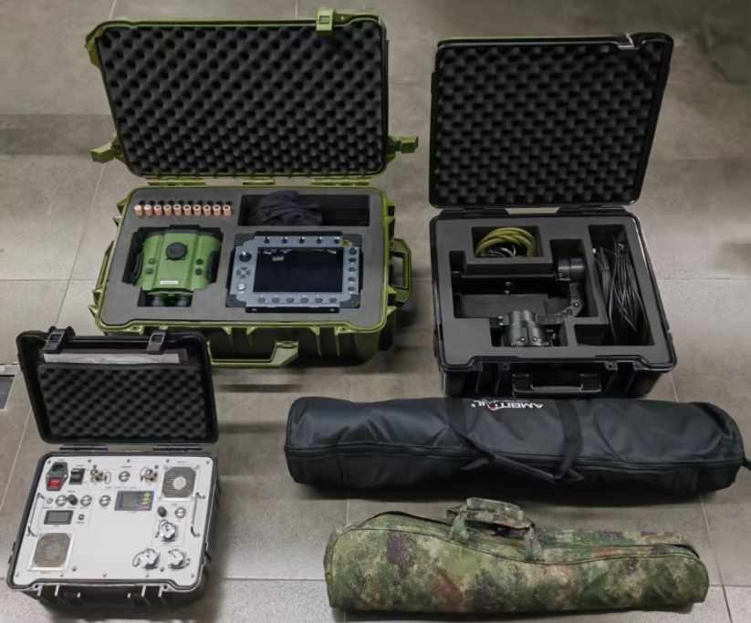
Figure 1 Composition diagram of handheld anti-reconnaissance system
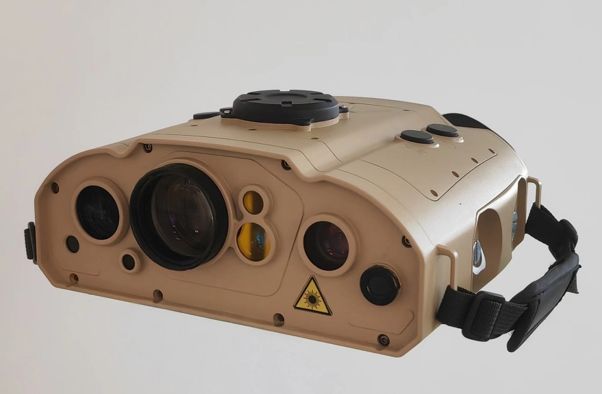
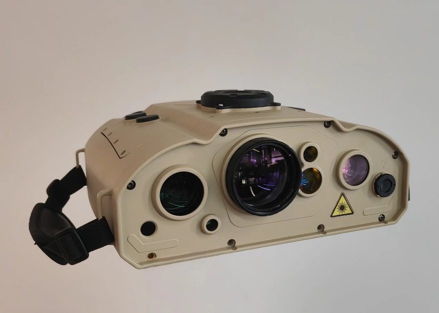
Figure 2 Front view of handheld anti-reconnaissance system
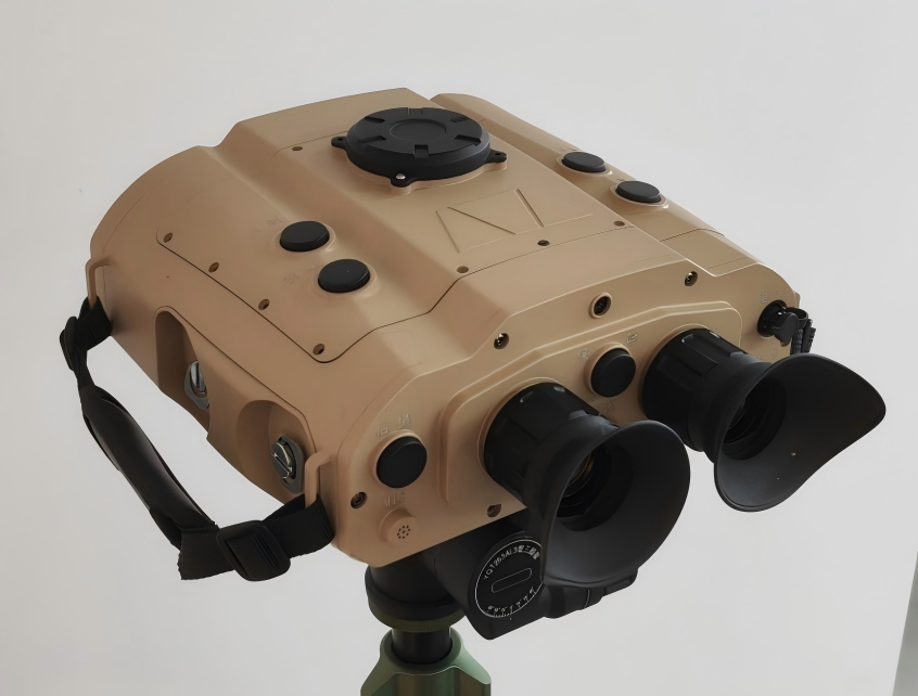
Figure 3 Rare view of handheld anti-reconnaissance system
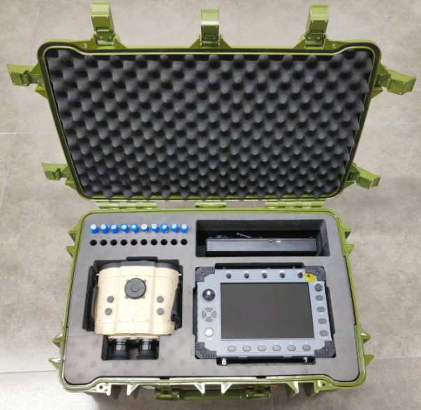
Figure 4 Packing diagram for equipment and display & control terminal
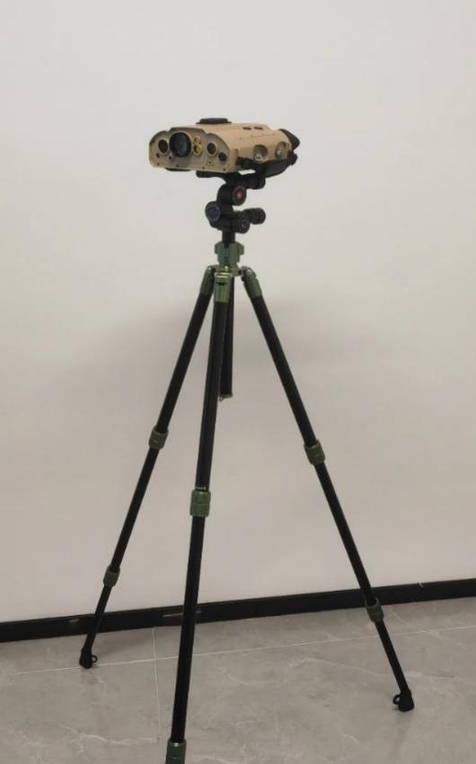
Figure 5 Setting up and using on a tripod
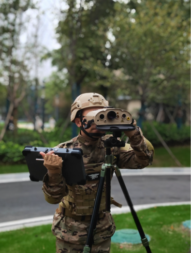
Figure 6 Combination of equipment and handheld display and control terminal
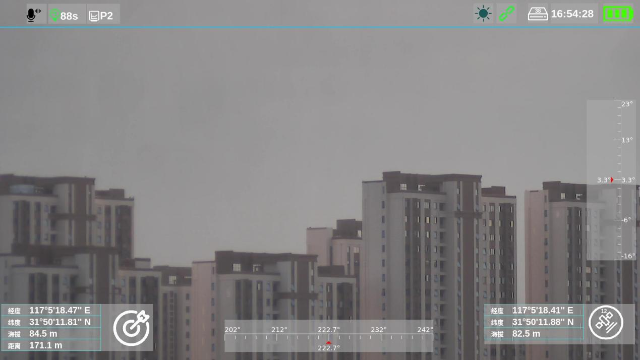
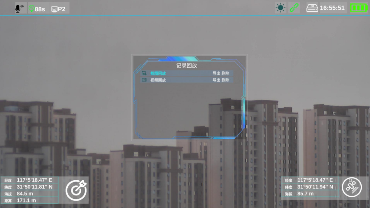
Figure 7 Operating interface of the equipment
3.Main Technical Specifications
a)Detection distance: ≥1200m(target lens aperture≥50mm) ;
b)Detection wavelength:≥800nm;
c)The identification distance of upright individual soldier is ≥1200m during the daytime and ≥400m at night;
d)Laser suppression capability
1)Laser band: 520nm;
2)Spot diameter: ≥50cm;
3) Suppression effect: glare to the human eyes, interference to the electronic sight pictures.
e)Measuring range:50m~3000m;
f)Laser alarm capability: it can range laser alarm from 0.9μm to 1.6μm band;
g)The self-positioning accuracy is not greater than 1.5m (CEP), and the target positioning accuracy is not greater than 30m (CEP);
h)Provided with voice recognition capability;
i)Host weight: ≤2.6kg;
4.Application scenarios
4.1 Anti-terrorism and urban warfare
In anti-terrorism and urban warfare, it can detect the location of snipers, conduct laser suppression, and guide firepower attacks.
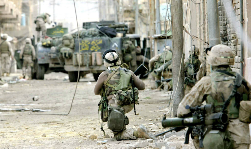
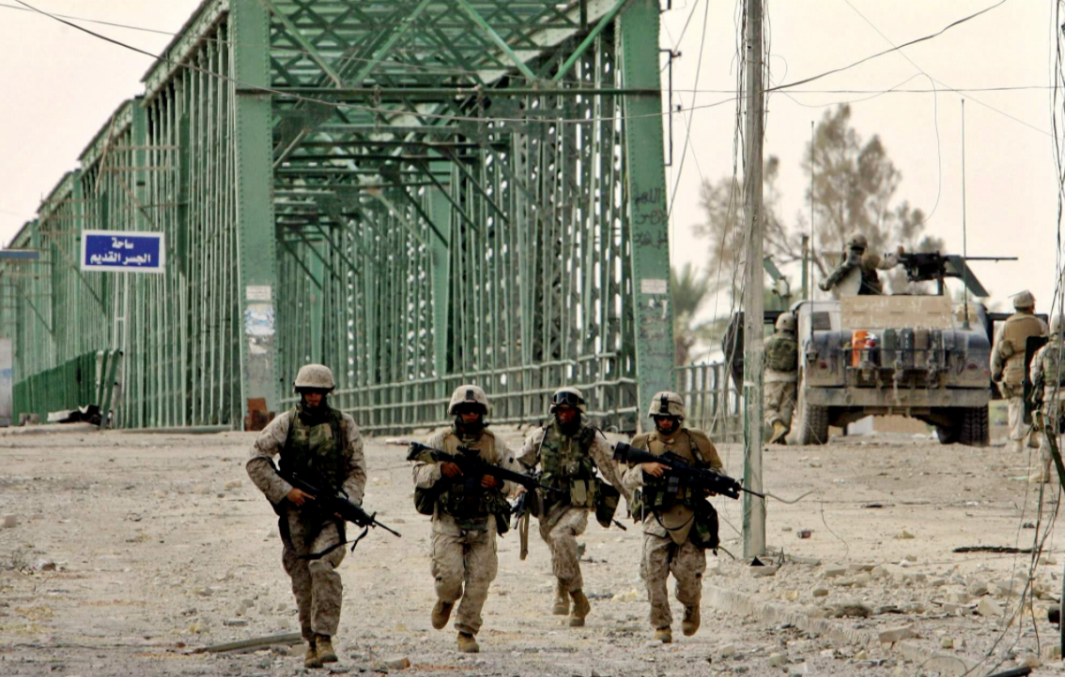
Figure 8 Scenario diagram for anti-terrorism and urban warfare
4.2 Airports, ports, missile positions, and other military areas
It can be used for anti-espionage surveillance and covert photography in various military areas, such as airports, ports, missile positions, and key confidential units.
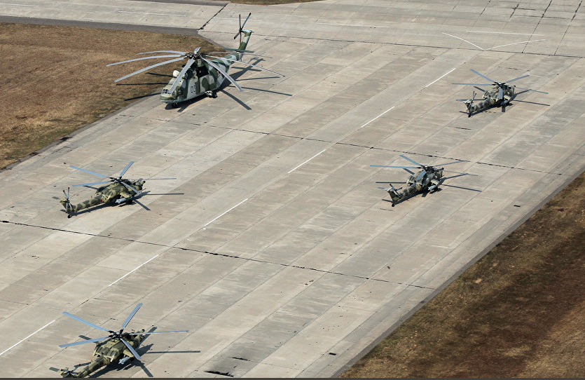
Figure 9 Usage scenario diagram of the airport
4.3 Major gatherings attended by important personnel
It can be used for on-site security at major gatherings attended by important personnel.
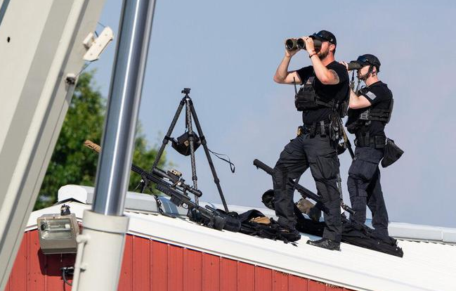
Figure 10 Scenario diagram for major gatherings in which key personnel participating
5.Mounted working status
Under the mounted working status, the equipment is used combining with the ring arm turntable, the distribution box, and the handheld display and control terminal. The handheld display and control terminal can be operated at a certain distance from the host, which enhanced the automation level of the equipment and improved the safety and comfort of the operators. The specific workflow is as follows:
a)Set up a medium-sized tripod (A lightweight turntable can also be used) and fix the ring arm turntable to the tripod via a mechanical interface.
b)Fix the host on the connecting support plate of the ring arm turntable through a mechanical interface, and connect the electrical interfaces of the host and the turntable with a dedicated cable.
c)Unfold the tap box and the handheld display and control terminal, and connect the electrical interfaces of the turntable, tap box, and handheld display and control terminal with a dedicated cable to achieve power supply and communication.
d)Separately turn on the power supply switch, working switch, communication switch, and turntable working switch of the distribution box to achieve self-power supply and power supply to the turntable, and to ensure smooth communication channels with the turntable and handheld display and control terminal.
e)Press and hold the power button on the host for 2 seconds to turn it on and open the lens protective cover; press and hold the power button on the handheld display and control terminal for 2 seconds to turn it on, and the screen will display the images and overlay information transmitted from the host.
f) Operating the joystick handle of the handheld display and control terminal can control the azimuth and pitch rotation of the turntable, thus enabling panoramic observation. When precise ranging and targeting are required, the four-direction button can be used to slowly move the turntable for aiming.
g)Respectively turn on the handheld display and control terminal's rotating platform, detection, ranging, and suppression to enable the switches to be toggled.h) The host can be operated remotely by using the detection, ranging, suppression, black and white/color button configurations on the handheld display and control terminal. For specific details, refer to the workflow of the handheld operating state.
i)Turn on the antenna working switch of the distribution box and the antenna enable switch of the handheld display and control terminal respectively. The handheld display and control terminal can also communicate with the distribution box by wireless, controlling the turntable and the host, further enhancing the concealment and safety of the operator.
j)After the work is completed, shut down all components, remove the cables, disconnect the mechanical interfaces of each component, place each component into its carrying case, and then the dismantling is complete.
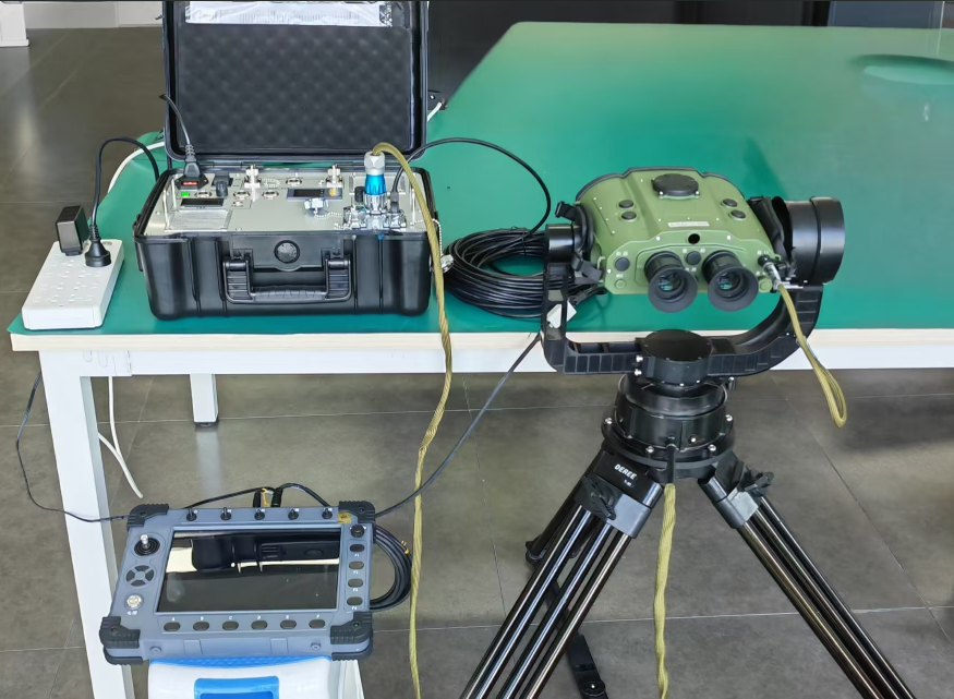
Figure 11 Erection work status diagram


